
Deraj_53's Project GC

Registered User
iTrader: (26)
Joined: Mar 2004
Posts: 7,140
From: buying a house in hawaii is harder then it looks
Car Info: 2001 Impreza 2.5RS-T 2011 Forester Prem. SUBYS FTW
hmmm what year is this from? that looks like the 06+ style. i know when we did astins 06 conversion his was the pull type without the cotter pin. and it looks like yours so you may need a 06+ axle.
Thread Starter
Registered User
iTrader: (5)
Joined: Apr 2006
Posts: 824
From: Kapolei
Car Info: 1998 RS STi
Its a 2003 JDM Sti 6-speed and uses the male front drive axles (yea the ones without the pin that just pull out)
I believe subaru switched to female drive axles in 04 briefly before switching back to male axles >_< making it a pita to find the correct one.
The problem was they shipped a 2004 motor and drivetrain components but a 2003 6-speed
If they had shipped a 2004 6-speed I wouldn't be having this problem possibly.
Any male 6-speed axles may work that's what I'm trying to find out.

You can use the 04 axle stubs for the transmission... and all their parts
see here:::
http://forums.nasioc.com/forums/show....php?t=1772793
Early 2004 Axle Seal Part Numbers (to be used with axle stubs / female axles):
Left: 806730041
Right: 806730042
and
TWO EACH
Axle Stub Part Number: 38415AA110
Circlip Part Number: 805329010
This is what I used in my 2008 USDM SpecB 6mt swap into my Unicorn

i used a punch.... just a note tho, make sure you put it back exactly where it was as it adjusts the front diff's hypoid gear backlash, and tooth contact... in a perfect world, you should re-adjust to specs once you touch it but that involves tearing apart your transmission.
ive included some info below for your reference, the steps are not in order, but is a incomplete guide for removing the front diff, again its just for your reference...
-------------------------------------------------------------------------
13. Using the ST, remove the axle shaft. ST1 499247300 INSTALLER ST2 499095500 REMOVER ASSY NOTE:
*Do not reuse the circlip.
*Mark to identify the right and left axle shaft.
14. Using the ST, remove the differential side retainer on both sides. ST1 499787000 WRENCH ASSY (RIGHT SIDE) ST2 18630AA000 WRENCH ASSY (LEFT SIDE) NOTE: Be careful not to damage the part of clutch case where the retainer is to be installed.
15. Remove the front differential.
INSTALLATION
1. Install the differential assembly into clutch housing.
2. Apply oil to the threaded portion part of side retainer.
3. Remove the O-ring from side retainer of both sides.
4. Using the ST, install the differential side retainer to both sides. ST1 499787000 WRENCH ASSY (RIGHT SIDE) ST2 18630AA000 WRENCH ASSY (LEFT SIDE) NOTE: Be careful not to damage the oil seal.
5. Install the axle shaft. NOTE:
*Replace the circlip with a new one.
*Be careful not to confuse right and left axle shaft.
*Wrap vinyl tape around the spline part of axle shaft.
6. Check and adjust the hypoid gear backlash.
7. Check and adjust the tooth contact.
8. Mark an engagement point on the right and left side retainer and clutch housing.
9. Remove the differential side retainer from both sides. NOTE: Note the rotating number of time till removal, when removing the side retainer.
10. Install a new O-ring to side retainer of both sides.
11. Install the differential side retainer to both sides. NOTE: Install the side retainer by screwing in the same rotating number of time till removal, and then align the mark.
HYPOID GEAR BACKLASH
Check the hypoid gear backlash. If it is not within specifications, adjust it.
TOOTH CONTACT OF HYPOID GEAR
1. Be sure the hypoid gear backlash is within specifications. If it is not within specifications, adjust it.
2. Apply a uniform thin coat of red lead on both tooth surfaces of three or four teeth of the hypoid driven gear.
3. Install the drive pinion shaft assembly, and then secure it with four bolts. NOTE: Use the old gasket and washer to prevent the mating surface of housing from damaging. Tightening torque: 50 Nm (5.0 kgf-cm, 36.9 ft. lbs.)
4. Rotate the drive pinion shaft to right and left for several times.
5. Remove the drive pinion shaft assembly, and then check tooth contact. If tooth contact is inaccurate, adjust it.
*Correct tooth contact.
NOTE: Under no load, tooth contacts50 - 60% from center to toe side (tooth contact shifts to heel side when driving).
ADJUSTMENT
HYPOID GEAR BACKLASH
1. Install the right and left side retainer. ST1 499787000 WRENCH ASSY (RIGHT SIDE) ST2 18630AA000 WRENCH ASSY (LEFT SIDE) NOTE: Screw in the right side retainer a bit further than left side.
2. Install the drive pinion shaft assembly, and then secure it with four bolts. NOTE: Use the old gasket and washer to prevent the mating surface of housing from damaging. Tightening torque: 50 Nm (5.0 kgf-cm, 36.9 ft. lbs.)
3. Using the ST, screw in the left side retainer until the drive pinion and hypoid driven gear contacts lightly. Then loosen the right side retainer. ST1 499787000 WRENCH ASSY (RIGHT SIDE) ST2 18630AA000 WRENCH ASSY (LEFT SIDE)
4. Using the ST, rotate the drive pinion shaft several times. ST 18631AA000 HANDLE
5. Repeat step 3 and 4 until the left side retainer can not be rotated. For the right side retainer, screw it in until the inner race and outer race contacts lightly. This condition is "0" backlash.
6. Mark an engagement point on the right and left side retainer and clutch housing.
7. Return the left side retainer for three teeth, and screw in the right side retainer for three teeth.
8. Using the ST, secure the drive pinion shaft. ST 18621AA000 ADAPTER WRENCH
9. After rotating the drive pinion shaft several times, measure the hypoid gear backlash using the ST. ST1 498255400 PLATE ST2 498247001 MAGNET BASE ST3 498247100 DIAL GAUGE Hypoid gear backlash: 0.13 - 0.18 mm (0.0051 - 0.0071 inch)
10. If the backlash is out of specification, adjust it by turning the right and left side retainers.
11. Screw in the right side retainer for further 1.75 teeth. TOOTH CONTACT OF HYPOID GEAR Refer to the section of drive pinion shaft for checking of tooth contact.
Thread Starter
Registered User
iTrader: (5)
Joined: Apr 2006
Posts: 824
From: Kapolei
Car Info: 1998 RS STi
Yep I was going to put some marks on the retainers and the transmission and count the number of turns to take them off.
On the early JDM 6-speeds the retainers have to be taken off to replace the axle seals.
If I do one side at a time and mark the position of everything, in theory it should still be in spec when I put it back together.
On the early JDM 6-speeds the retainers have to be taken off to replace the axle seals.
If I do one side at a time and mark the position of everything, in theory it should still be in spec when I put it back together.

Thread Starter
Registered User
iTrader: (5)
Joined: Apr 2006
Posts: 824
From: Kapolei
Car Info: 1998 RS STi
Yup came in last week
now im just looking for a tool to take them off.
In the mean time I got some other stuff done.
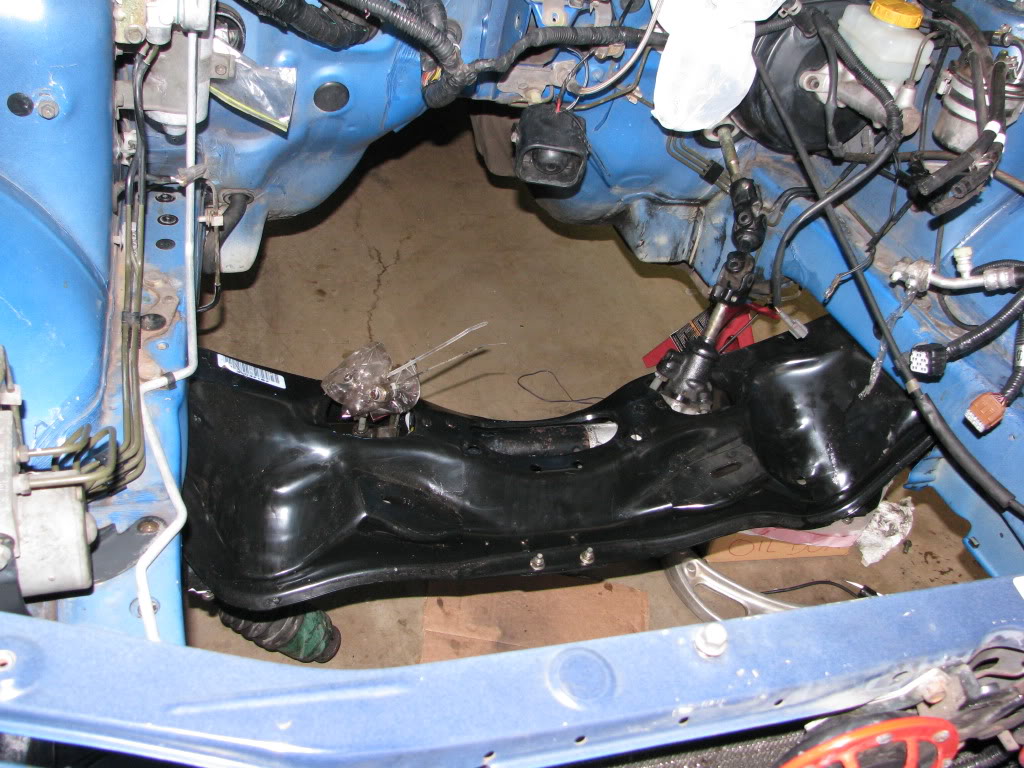
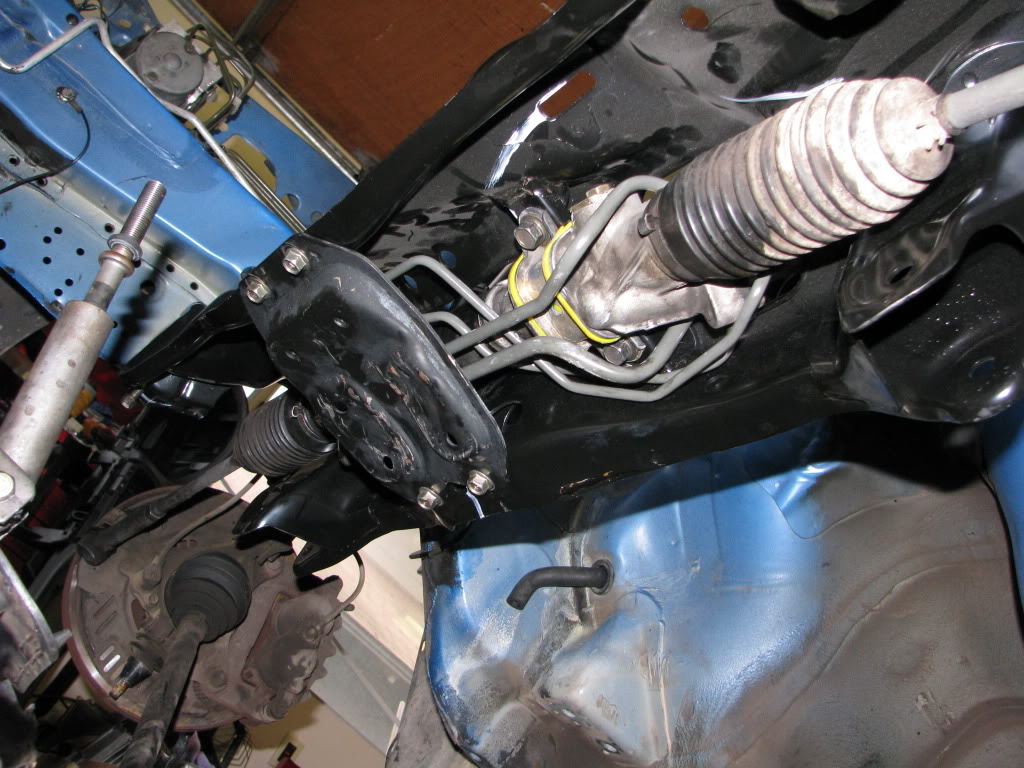
New Crossmember in and old steering rack mounted with whiteline bushings.
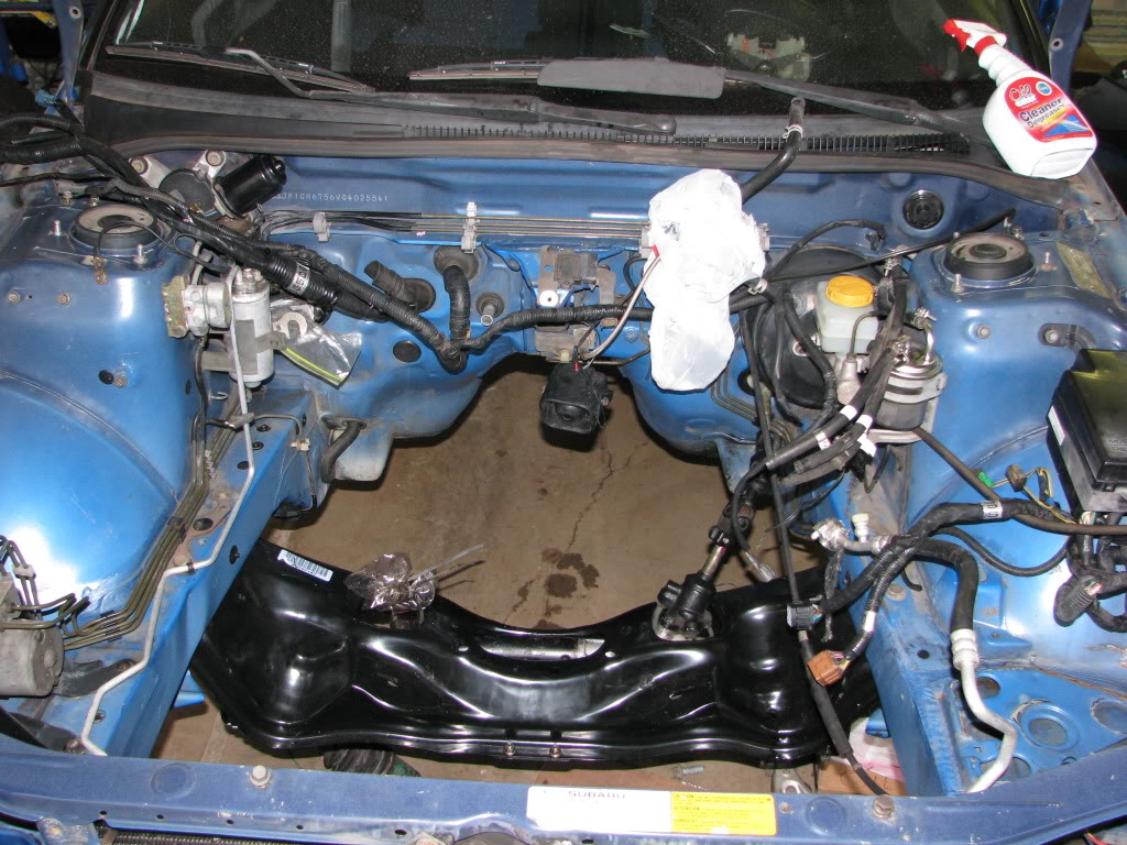
Also Cleaned up the Gunk and Oil in the Engine Bay
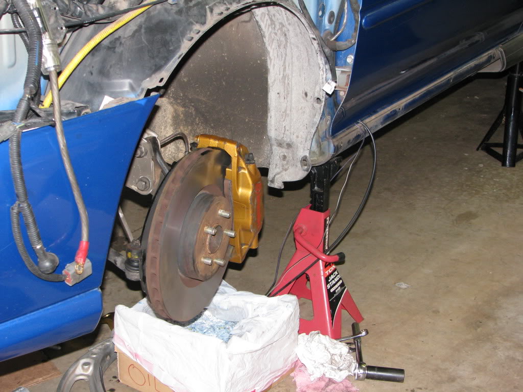
Got the Front Hubs on with the Brakes.
now im just looking for a tool to take them off.
In the mean time I got some other stuff done.
New Crossmember in and old steering rack mounted with whiteline bushings.
Also Cleaned up the Gunk and Oil in the Engine Bay
Got the Front Hubs on with the Brakes.
Registered User
iTrader: (3)
Joined: Jul 2004
Posts: 1,399
From: Finally runnin 285's
Car Info: Slower than the guy with all the money :(
Your car sucks!! J/K !!!!
Great job Jared,I really wish I built my car myself.
Oh well,the next phase of my car will be done mostly by myself.
Can't wait to see this beast run,you're gonna have to find some way to stuff some bigger tires under there.
You plan on autocrossing the car when it's done? Look forward to some battles!!
Registered User
iTrader: (33)
Joined: Nov 2002
Posts: 10,455
From: Boostin' troubles away - 4EAT Memories 12.87@103.2
Car Info: 51E LHD V7 STI (2.0)
eh try hurry up laddat! LOL
yay! another JDM buddy in Kapolei.
taking to long to many parts just sitting and not enough smiles on your face from driving it! hehehe
wiring is going to be a *****... how much research have you done on the wiring aspect. have you research getting your AVCS working? IA Performance might be able to help you with your AVCS portion you should look into it.
Thread Starter
Registered User
iTrader: (5)
Joined: Apr 2006
Posts: 824
From: Kapolei
Car Info: 1998 RS STi
Your car sucks!! J/K !!!!
Great job Jared,I really wish I built my car myself.
Oh well,the next phase of my car will be done mostly by myself.
Can't wait to see this beast run,you're gonna have to find some way to stuff some bigger tires under there.
You plan on autocrossing the car when it's done? Look forward to some battles!!
Great job Jared,I really wish I built my car myself.
Oh well,the next phase of my car will be done mostly by myself.
Can't wait to see this beast run,you're gonna have to find some way to stuff some bigger tires under there.
You plan on autocrossing the car when it's done? Look forward to some battles!!
The only problem with doing it yourself is it's really slow especially when you don't know what you are doing until you actually do it

And yes I plan on autocrossing it but its not gonna be an all out track car. I gotta DD this thing ya know.
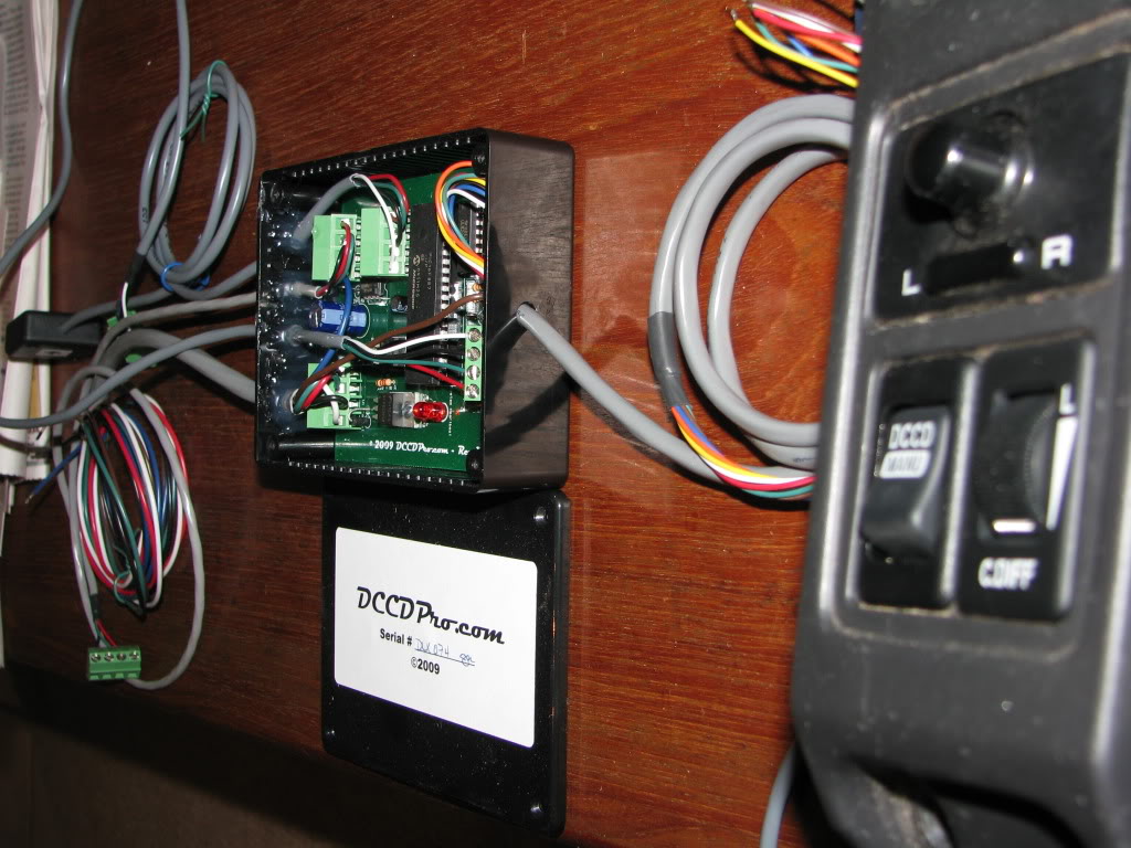
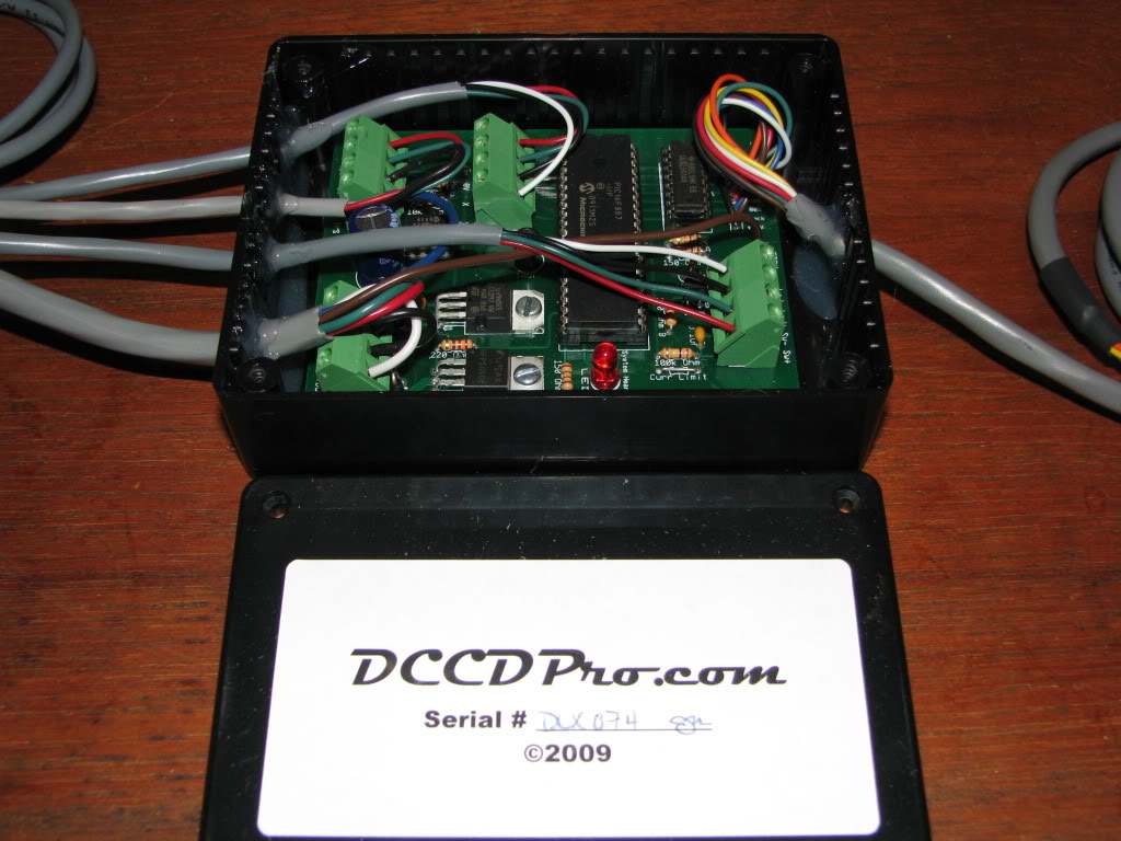
The wiring is almost finished, gotta re-hookup the alarm to the harness and finish wiring the fuel pump to the controller. And wire in this part thats been laying around for a while.
AVCS should be working as far as I know. Won't know for sure until its running. What I really need to finish is the transmission, getting those seals in so I can drop it in and start it up. So close >_< !!!
Registered User
iTrader: (33)
Joined: Nov 2002
Posts: 10,455
From: Boostin' troubles away - 4EAT Memories 12.87@103.2
Car Info: 51E LHD V7 STI (2.0)
what ECU are you using? if you're using the JDM ECU did you wire in the AVCS? what dash harness are you using since I didn't see you mention it. If you're using a WRX dash/car harness then you can buy a AVCS wiring kit that will integrate into the brown and grey connectors in the engine bay (drivers side behind the battery) which will activate the AVCS. The place that sells the harness if you don't have it is IA Performance (http://www.iaperformance.com/product...0859d0b577e736). Take a look if you haven't wired this up. The AVCS is one of the reasons to get a JDM engine 
This will only work if you're using a JDM ECU though.
which spiider controller did you get?
This will only work if you're using a JDM ECU though.
which spiider controller did you get?
Last edited by iNfEk; Sep 8, 2009 at 10:55 AM.