
question!

Registered User
iTrader: (2)
Joined: Sep 2006
Posts: 1,049
From: Ewa Beach Hawaii
Car Info: 2015 CWP STI
Joejoe's DIY Air Oil Separator
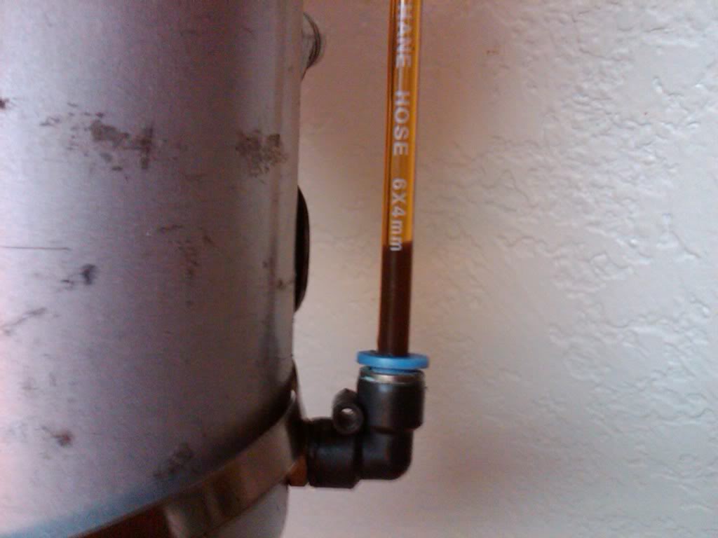
Bringing this thread back from teh dead. Yes, TEH dead!! I just realized my previous catch tank setup sucked ***. It did a good job catching the oil, but the oil just stayed in the can and my motor lost a good amount, say half a quart in a month or so. Here is the level on the oil 'catch' tank:
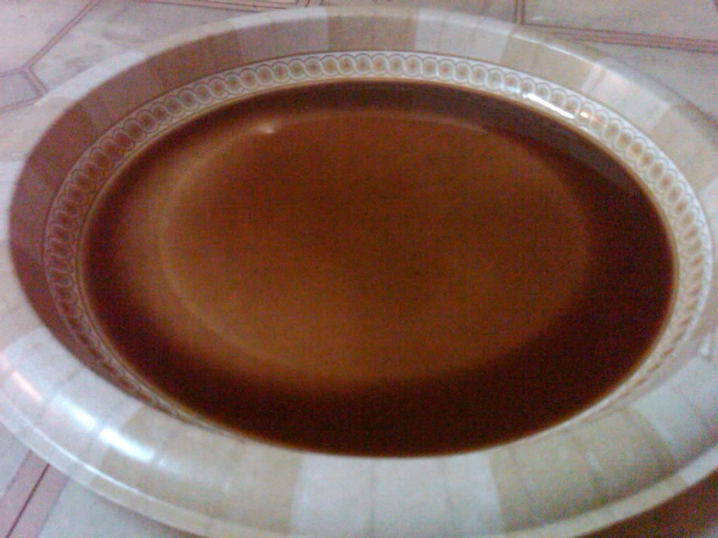
Here's the $hit drained on a paper plate, that goes into your intake, turbo, intercooler, and eventually your combustion chamber, which lowers your octane, and consequently causes knock, IF you run your car hard without some sort of oil separation thingamajig:
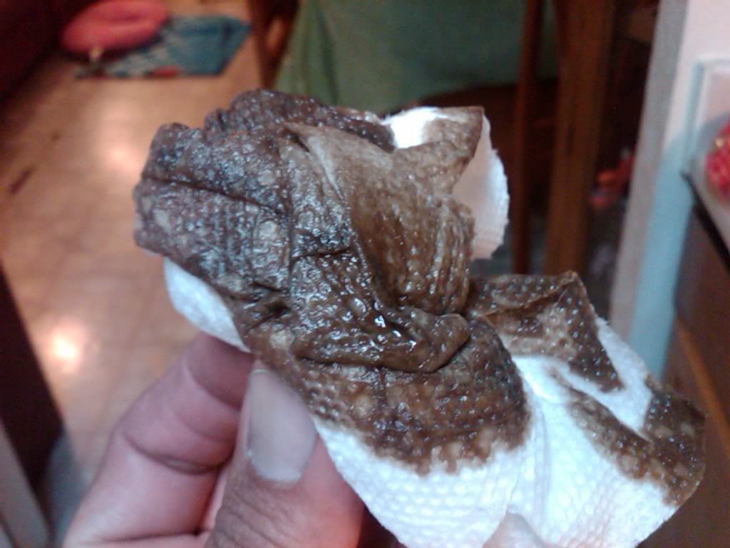
The same $hit wiped up. This is the reason why you use Techron or Shell V-Power:
Now here's the newly designed DIY closed loop air oil separator made from a 0.5L aluminum can from ebay, aircraft fittings and hose ends, steel mesh, clear braided hoses, and ESH TIG-welding:
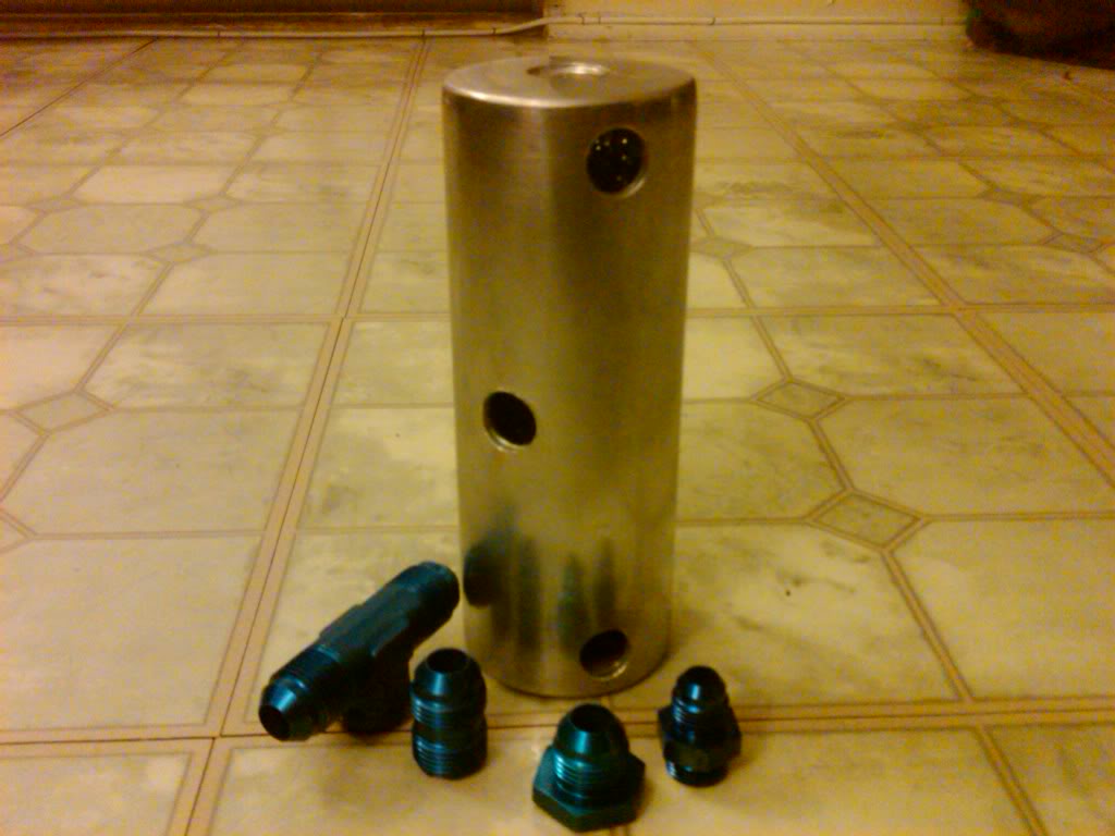
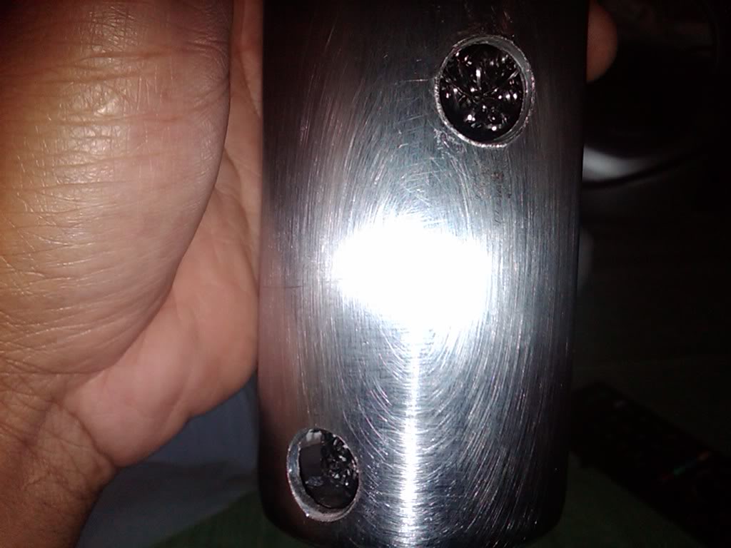
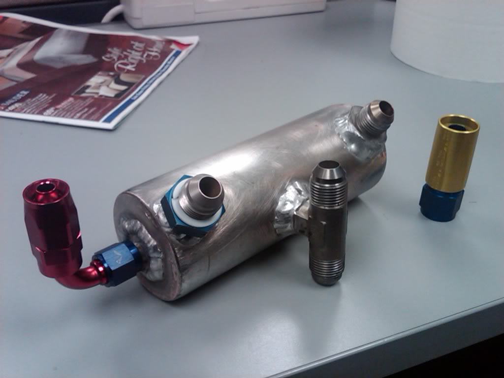
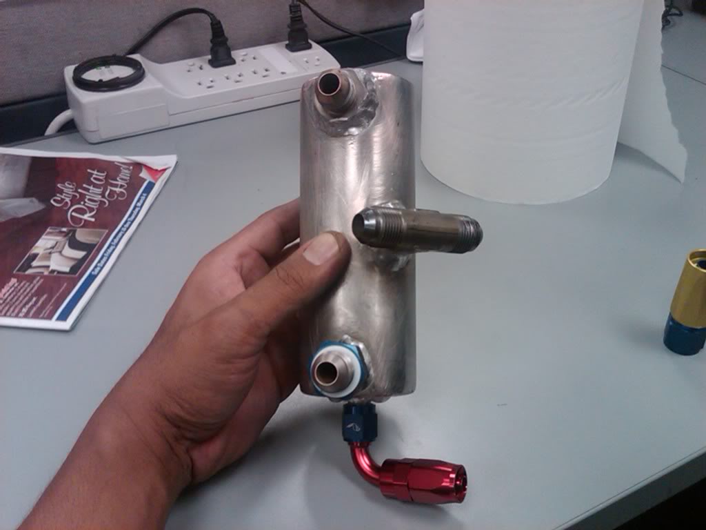
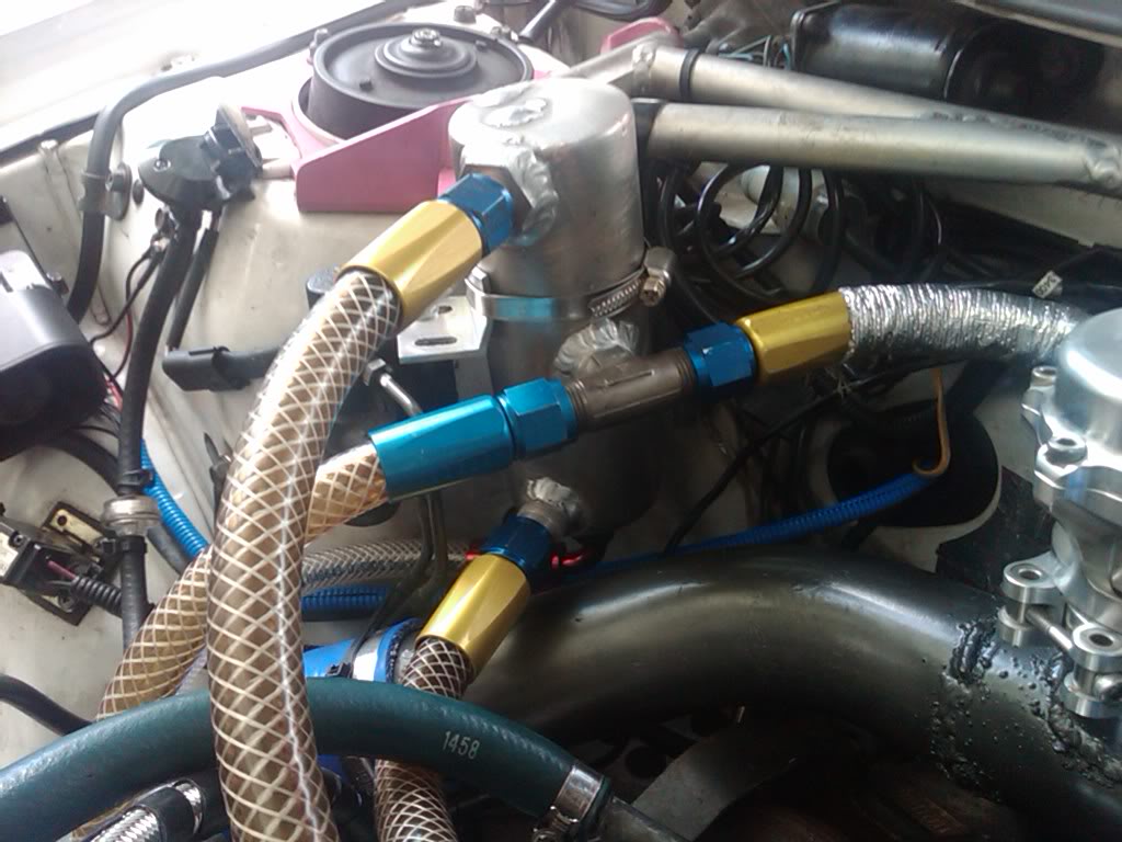
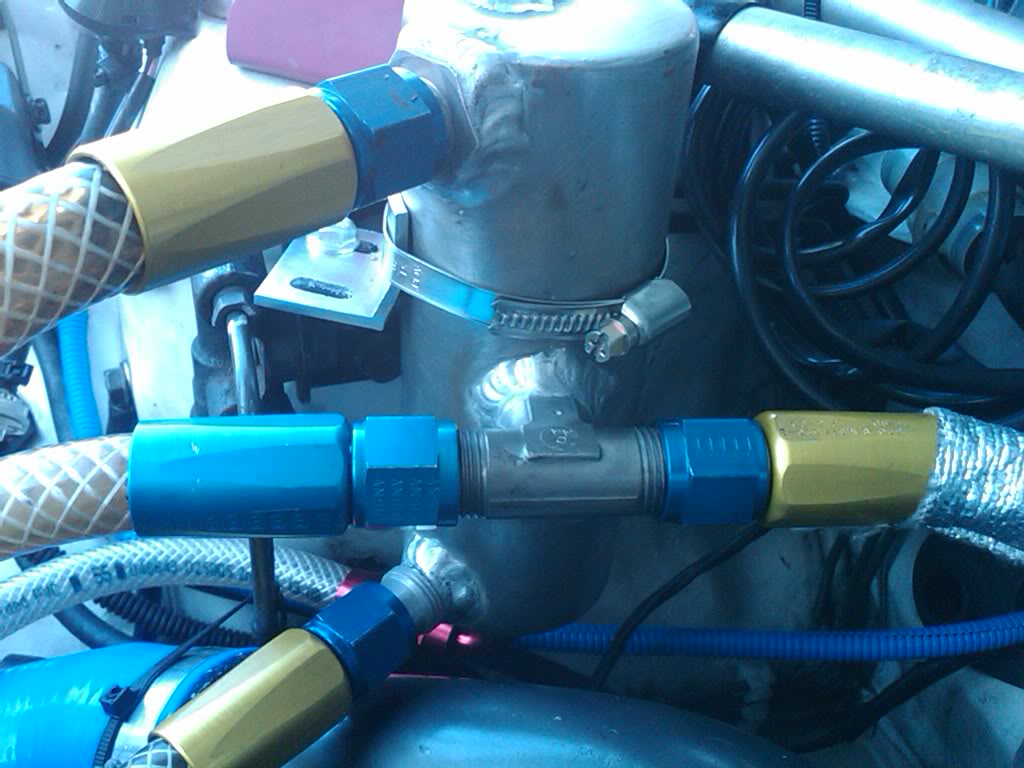
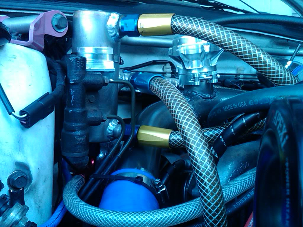
Here's how it works, the T-fitting in the middle comes from both L/R valve covers, the lower fitting comes from the crankcase vent. The inside mesh takes up about almost 2/3s of the can and catches the oil and blow-by. The rest of the gases is sucked up and out from the top fitting into the turbo inlet, then the oil is returned from the very bottom fitting into the crankcase vent side nipple. No milky yellow sludge building up inside like the $385 Crawford unit, no oil loss, no oily turbo inlet/turbo/intercooler, no knocking, no problem. Oh btw, my PCV valve is non-existent in this system for my blow-through MAF setup. Way easier to tune.
Cost: $60
FWIW: Priceless
Here's the $hit drained on a paper plate, that goes into your intake, turbo, intercooler, and eventually your combustion chamber, which lowers your octane, and consequently causes knock, IF you run your car hard without some sort of oil separation thingamajig:
The same $hit wiped up. This is the reason why you use Techron or Shell V-Power:
Now here's the newly designed DIY closed loop air oil separator made from a 0.5L aluminum can from ebay, aircraft fittings and hose ends, steel mesh, clear braided hoses, and ESH TIG-welding:
Here's how it works, the T-fitting in the middle comes from both L/R valve covers, the lower fitting comes from the crankcase vent. The inside mesh takes up about almost 2/3s of the can and catches the oil and blow-by. The rest of the gases is sucked up and out from the top fitting into the turbo inlet, then the oil is returned from the very bottom fitting into the crankcase vent side nipple. No milky yellow sludge building up inside like the $385 Crawford unit, no oil loss, no oily turbo inlet/turbo/intercooler, no knocking, no problem. Oh btw, my PCV valve is non-existent in this system for my blow-through MAF setup. Way easier to tune.
Cost: $60
FWIW: Priceless
Last edited by joejoe69; Mar 10, 2010 at 03:36 AM.

Thread
Thread Starter
Forum
Replies
Last Post
brucelee
Bay Area
12
Aug 1, 2009 10:59 AM
legacy2003
Interior, Exterior & Lighting
6
Jun 8, 2003 04:43 AM