The quest for better interior lighting revisited (inst. for Direct Replacement LEDs)
 04-28-2005, 04:04 AM
#151
Guest
Posts: n/a
I have done mine using red bulbs (not LEDs). I fabricate a connections of 3 bulbs in parallel wiring. Blue is not a dominant color compare to red, the needle will definitely not light up well. Btw, mine is a MY03 wrx. Hope to see some pics of your works.....Good luck guys.

 10-12-2005, 02:05 PM
#153
Registered User

Join Date: May 2005
Location: So. Cal
Posts: 62
Car Info: 05 obp WRX
looks great! I've been getting tired of OEM green interior lights.
This is definately on my "To do List". Thanks for the great write up
I've looked at couple of interior pictures in this post, can't really decide
on what color to go for. I-club members who has done this mod, possible to post
more pictures?
This is definately on my "To do List". Thanks for the great write up
I've looked at couple of interior pictures in this post, can't really decide
on what color to go for. I-club members who has done this mod, possible to post
more pictures?
10-26-2005, 02:10 AM
#154
Registered User
iTrader: (7)

Join Date: Feb 2004
Location: Winter Wonderland
Posts: 110
Car Info: MOAR RUBBER THAN YO MOMMY'S SUV
What the heck!!!! I bought the #74 bulb for the key halo and the tutorial said it will fit without modification but it didn't. I have a 03 wrx. The bulb did not want to go all the way in. Does someone one want to want to update this and provide pics of exactly what led bulbs are needed. I do not want to buy them and have the wrong ones cuz it seems like the website has updated with some new stuff and doesn't correspond to the year old directions
11-03-2005, 02:37 PM
#155
Registered User

Join Date: Oct 2005
Location: USA
Posts: 18
Car Info: Subaru
Does anyone thats done the Dash/ HVAC LED install know if the LED's cause a problem with the dimmer or if the dimmer still works--I know LED's light up with minimal power, so Im wondering if you are still able to dim the dash after this install---let me know! Thanks!!
11-03-2005, 04:08 PM
#156
VIP Member
Join Date: Apr 2004
Location: Sunnyvale
Posts: 726
Car Info: '99 Impreza OBS
Originally Posted by BlackFlame
Does anyone thats done the Dash/ HVAC LED install know if the LED's cause a problem with the dimmer or if the dimmer still works--I know LED's light up with minimal power, so Im wondering if you are still able to dim the dash after this install---let me know! Thanks!!
So in short, the dimmer still works
11-04-2005, 01:16 PM
#157
VIP Member
iTrader: (17)
Join Date: Jul 2004
Location: Northern California
Posts: 3,969
Car Info: 04 STi
I don't know if you guys have seen it, but autoluminations now offers a Neo Wedge Bulb, I bought a few of them to test them out. I'll let you guys know if it's a direct replacement for 04 HVAC. I'll have a friend with an 02 come around to see if they fit the 02/03/04 Speedometer Cluster.
Check out:
http://autolumination.com/74.htm
Check out:
http://autolumination.com/74.htm
11-07-2005, 11:19 AM
#158
Registered User
iTrader: (1)

Join Date: Oct 2003
Location: Israel, Herzelia
Posts: 135
Car Info: Impreza 1.6 Automatic gear
Hey Onizuka let me know how it turns out! I really wana change my color since i got my 02 impreza (4 years allready?!) but becuse of the moding to the elctricty you had to do I decided to wait untill there will be a better way. this bulbs are sepost to be a direct replacment right? they sure looks like it.
12-06-2005, 09:56 AM
#159
Registered User

Join Date: Nov 2005
Location: Jackson, MI
Posts: 2
Car Info: 02 WRX World Rally Blue
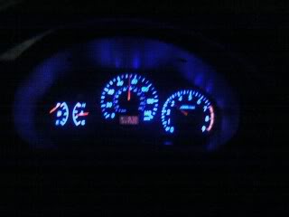
using blue LEDs
If you don't mind wiring up the LEDs separate from the rest of your gauges the outcome is pretty good I think especially if you want to retain the illumination of your needles. I used some blue gels for stage lights and nine (9) 5mm blue LEDs behind both the spedo and tach and three (3) behind the gas and temp gauge. First I scraped off the green film and cut out the blue gels to fit behind the stock gauge face leaving the red areas exposed, I also didn't remove the film behind the red areas. Next I soldered together (3) LEDs in series with a 510 ohm resistor and ran wires out of the cluster. Make 7 of these circuits. You will also need to sand the LEDs flat to get better light diffusion, I also scuffed up the sides to make them totally frosted. Arange your LED circuits in a ring behind your gauge inside of the cluster after you take the gauges themselves out. Make sure that you face the LEDs toward the engine bay! Yes that's right face them backwards... this eliminates hot spots and gives better light diffusion. After you install these rings and secure them, install the gauges back in the cluster. You will now have a mass of wires hanging out of your cluster make sure to remember which ones are positive and which ones are negative and connect all the positives together and all the negatives together and run + and - wires to the black (-) and light purple (+) wires on the far right cluster wire harness (this was in an 02'). Here's how it turned out....
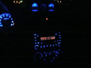
I also soldered in some LEDs into my stereo, gauges, and HVAC... not bad eh?
I also soldered in some LEDs into my stereo, gauges, and HVAC... not bad eh?
 02-02-2006, 03:36 PM
#161
Registered User

Join Date: Nov 2003
Posts: 128
Car Info: 03 RS- aspen white, 5 speed
i tried this with drop in replacement units, was not happy with the results(even after acetone/sandpaper to make the faces clear of green)
i'm going to be soldering in rings of single LEDs...
is the resistor necessary or will it work okay without as long as you add the proper number of LEDs in series?
here's some info i found-
http://www.theledlight.com/ledcircuits.html
also i want to retain the ability to dim them, if i solder into the stock illumination leads will i be able to dim them?
02-02-2006, 04:06 PM
#162
VIP Member
Join Date: Apr 2004
Location: Sunnyvale
Posts: 726
Car Info: '99 Impreza OBS
cation, i know u posted that a while ago (almost 2 months i guess) but i didn't respond as I was hoping someone else would ask... I must say though that it looks very nice.
1) How did you scrape off the green film from the gauges? did you leave them on and scrape behind with something? or take off the needles? or... I'm assuming you didn't take off the needles as all the problems I've read about would suggest that isn't a viable option.
2) blue gels? I'm assuming thats some kind of blue film that replaced the green from your description, and searches suggest that its some kind of theatre stuff, but could you confirm this? or perhaps better yet give a link?
3) and finally, the blue leds were truly necesary? I'd think replacing the green film with blue would make it so that the stock lights would light it up perfectly fine? were the gels to dense or...?
Thanks
02-06-2006, 12:03 AM
#164
Registered User
Join Date: Nov 2003
Posts: 128
Car Info: 03 RS- aspen white, 5 speed
okay- so i made an LED circuit to brighten and even out the cluster illumination since the red was faint and blotchy even with the entirely scratched out green film on the back of the faces.
i'll tell you upfront, i failed in my attempt. the placement of my led's along with the craftsmanship of the wiring made my dimspots into hotspots and instead of dim blotchyness i have bright blotchyness.
while i did fail at my goal, it's actually pretty cool and i'm sure with another couple tries i can make this setup pretty sweet.
first off the circuits- i used LEDs from LEDtronics, which were 12.50 plus shipping for a package of 25 LEDs. this isn't a terrible price, but it's not cheap either. the LEDs are 100mcd, "ultra-red" in color, and have 20mA current and 2.0 V forward voltage drop. they have a maximum operating voltage of 2.6V and a viewing angle of 110degrees. they have a flat top of the lens which is better for throwing light, at least i think.
i learned to solder while i did this project, and with the help of a friend who is an amateur(but very good) electrician/tech/computer technician/cool dude, i got pretty damn good at it. using 18g primary wire and my LEDs, i wired up some circuits with 330ohm, 1/4watt resistors in order to make sure the LEDs worked and have a better chance at dimming*(more on that later)
the circuits looked like this:
+12v side-----RESISTOR-----LED----LED----LED---- negative side
it's important to remember that LEDs are diodes and therefore directional- so the anode side, or plus side, must be facing the plus end of the circuit or the led won't light and won't pass current. for more on that, visit the link in my previous post on the last page.
when i finished soldering i insulated the leads with black electrical tape(THIS WAS A MISTAKE!!! use white components so there will be less absorption of light behind the cluster, it really makes a difference.) and made sure to label what side was plus and minus.
i ended up with five circuits of three LEDs- that's 15 100mcd LEDs completely devoted to making sure you can read your gauges

now for the hard part- putting the damn things in the cluster!!!!

here's pics of the cluster being disassembled... be sure to take off the back plastic too, as you'll need to unbend the tabs on the metal needle barrels behind each needle.


once you've unbent the tabs, pull on the clear plastic behind the faces and lift the needles and guages right up out of the cluster. you'll expose the white plastic that covers the circuit board and this is where you'll be positioning the LEDs. you'll also be able to see your existing bulbs/leds in the stock locations- this is a good way to find out how light gets dispersed through the stock cluster.
 02-06-2006, 12:04 AM
#165
Registered User
Join Date: Nov 2003
Posts: 128
Car Info: 03 RS- aspen white, 5 speed
you can see how the needle barrels connect on the three posts, with the two tabs unbent from behind you will be able to pull the whole face/clear plastic/needles off from the white circuitry and backing.


the most important part- positioning the LEDs in a way that will make the light even, dispersed, and not hot-spotted. i failed miserably at this.

here it is all ready to reassemble- i highly reccommend not doing it this way- because you will see how uneven the light is with some LEDs facing back, some front, and having black electrical tape that will absorb the light bouncing around in there...

reassembled the faces onto the cluster, with the wires routed out the back through two of the existing bulb holes(i just removed two of the bulbs...)


fully reassembled, now the rest of the wiring-

with five series circuits, only one is soldered parallel into another inside the cluster(be sure to solder them in parallel BEFORE the resistor and AFTER the last LED in the series), leaving virtually four series to be wired into parallel.
i had tested this out to make sure it would work prior to installing the circuits into the cluster.

putting it back into the car, with the final + lead and - lead running to the stereo harness-
